Quick Reference Guide to 10-Mbps Multi-Segment Configuration
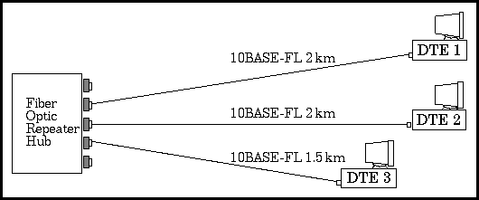
FIGURE 7.6 Simple configuration network
Even though this is a simple network, it is a configuration that is not described in the Model 1 canned configuration rules. Therefore, the only way to verify its operation is to perform the Model 2 calculations. By looking at the drawing, we see that the worst-case delay path is between DTE1 and DTE2, since this is the path with the longest distance between two DTEs. Next, let's evaluate this worst-case path for total round trip delay and interframe gap shrinkage.
Generated with CERN WebMaker